|
|
|
| *** Nice Weld Shame About The Fusion *** |
Today welding is the most common method used for joining steel fabrications largely because of the speed at which joints can be made and the reliability of these joints in service. However because most welding operations are now relatively simple to perform it is all too easy to forget the complexity of the chemical and metallurgical actions that are taking place when the weld is being deposited. Therefore not surprisingly welds occasionally fail.
The most common causes of weld failure can be attributed to one of the following causes:-
Overload.
Before applying the various design formulas, the problem itself must be analysed and clearly stated. This is not always obvious, and trying to solve the wrong problem can quickly lead to insufficient design stresses. When a load is placed on a member, stress and strain result. Stress is the internal resistance to the applied force. Strain is the amount of "give or deformation caused by the stress, such as deflection in bending, elongation in tension, contraction in compression, and angular twist in torsion. |
For example of this is a lifting lug on a pressure vessel. If the vessel is lifted by a spreader beam the loading condition on the lug consists of a simple vertical force putting the attachment welds either in tension or shear. However if the vessel is lifted with a rope sling the loading condition becomes more complex because there is now a horizontal component of the force to consider as well a the vertical one, which effectively increases the loading on the welds.
Joint Design.
A welded joint should be designed such that the welder can easily manipulate the electrode to ensure good fusion, particularly in the root of the joint. The profile of each run should be roughly as wide as it is deep; wide shallow weld beads and particularly deep narrow beads are both ideal candidates for hot cracking. |
 |
|
This type of cracking occurs when the weld is starting to solidify, in the pasty state, as it posses very little strength and therefore any residual loading is likely to cause it to break before it has fully solidified. The problem can be compounded by impurities that are forced out of the solidifying weld, becoming trapped in the centre of the weld during final solidification. Hot cracking can occur where their is a high degree of restraint in the structure of the fabrication or where the structure moves slightly as the weld solidifies. |
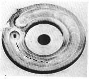
| A good example of this type of failure is on the weld used to secure the small plug in the mandrill hole of a spun dished head on a pressure vessel, a weld that many people do not take seriously because of its size. As the weld cools it contracts causing the plug to move , if the weld at the other side of the plug is still solidifying it could easily fail. This is because of the very high contraction stresses generated by the plug as the weld starts to solidify. |
 |
|
|
Bad Welding Method.
It is very important when carrying out any welding to ensure that it is done correctly. Consideration has to be given to all aspects of the process and also the environment. Often welding has to be carried out under site conditions, the welding is often carried out in situation so that small general purpose electrodes are used resulting in low weld heat input which when combined with no preheat gives very rapid heat dissipation Which can create a hard micro structure particularly in the location of the heat affected zone. This along with high levels of residual stress will create the ideal condition for hydrogen  induced cracking, which although normally associated with high strength steels can occur in low carbon steels if the conditions are right. The resulting crack may not occur immediately the weld cools down but some time afterward, therefore if this type of failure is expected non destructive examination should be delayed by at least 48 hours after welding. induced cracking, which although normally associated with high strength steels can occur in low carbon steels if the conditions are right. The resulting crack may not occur immediately the weld cools down but some time afterward, therefore if this type of failure is expected non destructive examination should be delayed by at least 48 hours after welding. |
|
|
Metallurgical failure.
Materials that are to be welded have to tolerate severe thermal transients created by the welding process without suffering deterioration of their mechanical properties or adverse phase changes. The metallurgical composition or temper conditions of certain types of metal may make them unsuitable to weld or may require special controls to be imposed during the welding operation. For example some steels that are easy to machine may contain high levels of sulphur that may result in cracking of any attaching weld. Therefore this type of material should not be used on load bearing fabricated items such as the eye bolts that are often found holding down manway covers on pressure vessels.
Weld Defects.
They can usually be attributed to the welders inability to set up and manipulate the welding equipment; although bad joint design and faulty welding equipment can also be responsible. The most significant defects are cracks and those that resemble cracks such as lack of fusion, cold overlap etc. This is because of the risk that the crack may become unstable and propagate when loaded causing a dramatic failure often by brittle fracture. |
 |
|
|
Porosity seldom causes weld failure in multi-run welds however it is a sign that something has gone wrong with welding operation and can often be caused by other defects that may not have been detected such as lack of side wall fusion. Weld profile can also cause failure, if the weld size is too small because the joint is underfilled with weld then its load carrying capability will be reduced, if the joint contains excessive weld metal this can create a notch effect which can lead to failure by fatigue if the loading condition fluctuates. Bad fit up excessive root penetration on single sided welds can create defects in the root of the weld such as wormholes and even cracking. Distortion of welded joints can cause failure by buckling if the welded member is subjected to compressive loads.
Guidance on imperfection levels of welded joints is given in EN 25817 {ISO 5817}
To minimise these problems the following points should be considered:- |
| 1. |
Design of the weld based on the loading condition(s) the joint will carry |
| 2. |
Accessibility to enable ease of welding |
| 3. |
Control of distortion |
| 4. |
Careful consideration of the welding environment |
| 5. |
Matching welding process with materials |
| 6. |
A factor of safty applied to the design stress of the weld which should be based on the consequance of weld failure and the level of non destructive testing that is to be carried out. |
|
|
For example a pressure vessel made to PD5500 category 3, (no radiographic inspection), can be up to twice a thick as an equivalent vessel made to category 2, (10% Radiography). Fillet welds and Partial Penetration welds should be used with care as they contain lack of fusion, they are only suitable for relatively low stressed joints that are not subject to any form of fatigue loading and should be used with a suitable factor of safety, which for fillet welds is at least two. |
| Once the weld has been designed it is then necessary to decide upon the welding method, this is then documented in the form of a welding procedure specification. The European Welding Standard for welding procedures, EN288 part 2, gives guidance on the content and format of such a specification. |
| However this document on its own is not sufficient because we need to prove that this welding method will produce a weld of acceptable quality possessing the right mechanical properties. Therefore it is necessary to simulate the joint in all essential features and weld it under normal production conditions. The completed joint can then be subject to both non destructive and destructive examinations to determine if the joint is going to be suitable for the application. |
| For most stringent applications the European Standard EN 288 Part 3 is preferred for welding procedure tests in steel materials and part 4 for Aluminium and its alloys. There are other parts of EN 288 that deal with alternative routes for qualifying procedures, other than a procedure test, for less onerous applications. See Welding Procedure Section for details. |
| Once we have established that the proposed welding method is satisfactory we then have to ensure that the production welds will also be of the same quality. This involves making sure the welders posses the required skill and knowledge to deposit sound welds in accordance with the approved procedure. Whilst we can be confident that the welder who did the procedure will be able, any other welder used must also demonstrate his ability by successfully completing a welder approval test. The preferred standard for this is EN 287 Part 1 for steel and part 2 for aluminium and its alloys. This standard not only tests the performance of the welder but also requires it to be monitored and revalidated every 2 years to ensure that the welders skill can be relied upon. |
| Finally make sure that when the welding operation is being carried out it is supervised and coordinated by properly qualified personnel. |
 How to Prevent weld failureالإثنين مارس 17, 2008 10:55 pm